Entertainment

Sabtu, 19 Maret 2011

Die Basic Part 6

This article is one of a 16-part series on the fundamentals of stamping. Descriptions of all the articles in this series, and links to them, can be found at the end of this article.

Previous articles in this series discussed common stamping die components. This article focuses on less common specialty components found only in certain dies, most of which are available from various suppliers.

Figure 1
Inidie Tapping Units
Image courtesy of Danly IEM.

In-die Tapping Units

Many dies produce parts that contain holes or extrusions that will be tapped or threaded to hold a fastener. These holes often are tapped in the die rather than in a separate, offline operation.

In-die tapping units use a series of helix-style shafts and gears to transfer linear motion (press ram) into rotary motion. The mechanical rotary motion can be press ram-driven, or it can be created by special electronic servo-drive motors. Besides moving downward, the tap spins and creates the threaded hole.

Unlike a regular cutting tap, an in-die tapping unit uses special roll forming taps. Instead of removing chips, roll forming taps gradually deform the metal into the shape of a thread. Using a standard cutting tap in an in-die tapping unit would create a cutting chip removal problem.

Because the work hardens during the metal deformation process, an in-die tapped hole's strength can be similar to a standard cut thread's strength. The difference is cost—using an in-die tapping unit instead of an offline tapping process can reduce costs significantly (see Figure 1).

Rotary Benders

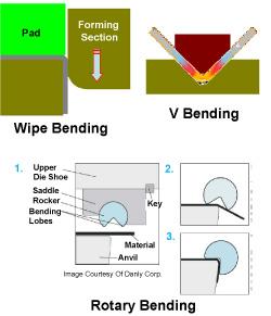
Figure 2
Image courtesy of Danly IEM

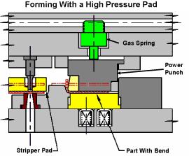
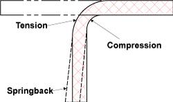
Rotary benders, often referred to as rocker benders, are specialty metal bending units that feature a rotary action-producing V-grooved cylinder. This cylinder is spring loaded and secured into a special retainer called a saddle. As the die closes and the cylinder makes contact with the sheet metal, it rotates about its centerline and creates the bend. Rotary benders can be used to create straight-line bends only.

Unlike conventional metal bending equipment, rocker benders require no additional pressure pad. Rocker benders can be easily adjusted and require less force than conventional bending methods. When inserted with a special hard plastic, they are nonmarking and can overbend the metal to create an acute or less than 90-degree angle. They also can create double bends (Figure 2).

Pierce Nut Units

Fasteners, such as screws, nuts and rivets, can be inserted into a stamped part in various ways. Using a pierce nut unit currently is a common method. This special mechanical unit (Figure 3) both pierces a hole and fastens a threaded nut to the stamped part.

Figure 3
Pierce Nut Installation Unit
Image courtesy of Multifastener Corp.

Pierce nut units can feed fasteners in several different ways and can be incorporated easily in progressive, line, and transfer dies. Unlike tapping, in which the hole relies on the amount of thread engagement that can be achieved by the specific extrusion length, pierce nut units can work with a variety of nut sizes, strengths, and thread series.

Pierce nut units can be used in almost any hole-piercing operation and are very popular in both the automotive and other industries.

HYDROCAMs

Activated by press ram-driven hydraulic cylinders, HYDROCAMs (Figure 4) pierce holes and create special forms in die areas that are inaccessible using standard cams. Using HYDROCAMs can reduce the number of stamping operations necessary, as well as the die cost.

Figure 4
HYDROCAM Assembly
Image courtesy of Ready Technology.

The drive unit can be placed almost anywhere beneath the press ram and can be used to activate one of several cams. Because these cams run on hydraulics, they can achieve a great force. HYDROCAMs also can be adjusted easily to fine-tune the timing to execute specialty cutting and forming operations.

Thread-forming Punches/Buttons

Thread-forming punches and buttons (Figure 5) both pierce and form the metal into a special shape. The specially shaped pierced hole functions to hold a variety of screws and increases the force necessary to pull the screw out of the sheet metal.

Figure 5
Image courtesy of Danly IEM.

The punches and buttons can be incorporated into standard ball lock retainers, or they can be the headed type. Because the metal simply is being pierced and formed, no press speed reduction is necessary.

Holes created with special thread-forming punches and buttons have improved holding ability over putting a screw into a flat piece of sheet metal.

Metal cutting and forming methods are virtually endless and limited only by the imagination. Each die has its own special function. To list all commercially available and custom-made die components available would be nearly impossible.

Die Basic Part 5

This article is one of a 16-part series on the fundamentals of stamping. Descriptions of all the articles in this series, and links to them, can be found at the end of this article.

Many specialty components can be used in dies, but the most commonly used are die plates, shoes, die sets, guide pins, bushings, heel blocks, heel plates, screws, dowels, and keys—all of which were explained in Part IV of this series. This article focuses on other common components—pads, retainers, and springs.

Figure 1

Pads

A pad is simply a pressure-loaded plate, either flat or contoured, that holds, controls, or strips the metal during the cutting and forming process. Several types of pads are used in stamping dies. Depending on their function, pads can be made from soft low-carbon steel or hardened tool steel. Contoured pads must fit very closely to the mating die section. Precision requirements determine whether the pads are positioned with guide pins and bushings or left unguided.

Stripper Pads/ Plates. Stripper pads are flat or contoured, spring-loaded plates that pull, or strip, the metal off the cutting punches. When it's cut, metal naturally tends to collapse around the body or shank of the cutting punches; this is especially true during piercing. The stripper pad surrounds the cutting punches and mounts to the upper die shoe. As the punch exits the lower die, the spring-loaded pad holds the metal down flush with the lower die section, which allows the cutting punches to withdraw from the sheet metal or piece part.

Often stripper pads are inserted with a small block of steel called a pad window. This pad window usually is small and lightweight and can be removed easily to allow the die maintenance technician to remove the ball lock-style pierce punch from the retainer without removing the entire stripper pad. Stripper pads also function to hold the metal flat or to the desired shape during the cutting process (Figure 1).

Pressure Pads/ Plates. During the wipe bending process, the metal must be held down tightly to the lower die section before the forming punch contacts the metal. Pressure pads must apply a force that is at least equivalent to the bending force. Most pressure pads use high-pressure coil or gas springs (Figure 1). When loaded with very high-pressure springs, contoured or flat pads also can form sheet metal. These pad types often are referred to as power punches (see Figure 2).

Figure 2Figure 3

Draw Pads. Draw pads control metal flow during the drawing process. In drawing, the amount of pressure, or downward force, exerted on the sheet metal determines how much metal is allowed to flow and enter the draw die cavity. Too much pressure may stop the metal from flowing and cause splitting; too little downward force may allow excess metal to flow inward and cause loose metal or wrinkling.

Draw pads, often referred to as binders or blank holders usually are made from hardened tool steel. They can be flat or contoured, depending on the piece part shape. Most drawing dies use a single draw pad; however, in special cases, some use two (Figure 3).

Spools, Shoulder Bolts, and Keepers

Spools, shoulder bolts, and keepers are used to fasten pads to the die shoes while allowing them to move up and down. They are secured to either the top or bottom die shoe with screws and often dowels for precision location. Of all of the components used for securing pads, spools are the most common, especially in larger dies (Figure 1 and Figure 4).

Figure 4

Retainers

Retainers hold or secure cutting or forming die components to both the upper and lower die shoes. One of the most popular retainers is a ball-lock retainer, a high-precision, accurately manufactured die component that secures and aligns both cutting and forming punches. It uses a spring-loaded ball bearing to locate and secure the punches, which feature a precisely machined teardropor ball seat. The spring-loaded ball bearing locks into the teardrop shape and prevents the punches from coming out of the retainer.

Figure 5

The advantage of ball-lock retainers is that they allow the die maintenance technician to remove and reinstall punches quickly. The punch is removed by depressing the spring-loaded ball bearing and pulling up on the punch. Specialty retainers also can be made to hold and align irregular punch shapes, as well as headed-style punches and pilot pins (Figure 5).

Springs

Springs supply the force needed to hold, strip, or form metal. Many different springs are used in stamping dies. Spring selection is based on many factors, including the required force and travel, the spring's life expectancy, and, of course, cost. Among the most popular are gas springs, which, when filled with nitrogen, can supply a great deal of force. They also have an excellent life expectancy.

Figure 6

Other types are coil and urethane springs, often called marshmallow springs (Figure 6). Coil springs are very popular when a reasonable amount of force is needed and budget constraints are present. Urethane springs work well in short-run or prototype stamping operations. They also are inexpensive.

Die Basic Part 4

Stamping dies can comprise many components. This article discusses the basic components, including die plates, shoes, die sets, guide pins, bushings, heel blocks, heel plates, screws, dowels, and keys. This article is one of a 16-part series on the fundamentals of stamping. Descriptions of all the articles in this series, and links to them, can be found at the end of this article.

While many specialty components can be used in manufacturing dies, most dies contain certain common components.

Die Plates, Shoes, and Die Sets

Figure 1
Various die set types

Die plates, shoes, and die sets are steel or aluminum plates that correspond to the size of the die. They serve as the foundation for mounting the working die components. These parts must be machined so that they are parallel and flat within a critical tolerance. The machining methods are milling and grinding. Although grinding is the most popular, a milled surface now can be obtained that is as accurate as a ground surface.

Most die shoes are made from steel. Aluminum also is a popular die shoe material. Aluminum is one-third the weight of steel, it can be machined very quickly, and special alloys can be added to it to give it greater compressive strength than low-carbon steel. Aluminum also is a great metal for shock adsorption, which makes it a good choice for blanking dies.

The upper and lower die shoes assembled together with guide pins create the die set. The lower die shoe often has machined or flame-cut holes that allow slugs and scrap created in the die to fall freely through the die shoe onto the press bed. The holes also may serve as clearances for gas springs and other die components.

The die shoe thickness is based on how much force can be expected during cutting and forming. For example, a coining die, one that compresses metal by squeezing it between an upper and lower die section, requires a much thicker die shoe than a simple bending die (see Figure 1).

Guide Pins and Bushings

Guide pins, sometimes referred to as guide posts or pillars, function together with guide bushings to align both the upper and lower die shoes precisely. They are precision-ground components, often manufactured within 0.0001 in. Although numerous specialty mounting methods can be used to install these components, there are only two basic types of guide pins and bushings—friction pins and ball bearing-style pins.

Friction pins are precision-ground pins that are slightly smaller than the guide bushing's inside diameter. Pins are made from hardened tool steel, while bushings often are made from or lined with a special wear-resistant material called aluminum-bronze. The aluminum-bronze may contain graphite plugs that help to reduce friction and wear that occur to the pins and bushings.

Friction pins also help to heel the die shoes and prevent them from moving from side to side.

Figure 2
Various guide pins and bushings

Precision or ball bearing-style guide pins comprise precision-hardened pins, ball cages, ball bearings, and bushings. Unlike friction pins, these pins ride on a series of ball bearings contained in a special aluminum ball cage that permits the bearings to rotate without falling out. These pins have several advantages. First, friction is reduced so the die can run at faster speeds without generating excessive friction and heat. Second, they allow the diemaker to separate the upper and lower die shoes easily. Third, because they use ball bearings, they can be manufactured with greater accuracy than friction pins (see Figure 2).

Remember, guide pins are meant to align the upper and lower die shoes, not to align a poorly maintained or sloppy ram in a press! Some companies try to compensate for a poorly maintained press by adding oversized guide pins or grinding the guide pin ends to a cone shape. Care must be taken when flipping die shoes over so that the guide pins are not bent.

Heel Blocks and Heel Plates

Figure 3
Heel blocks

Heel blocks are special steel blocks that are precision-machined, screwed, doweled, and often welded to both the upper and lower die shoes. They contain components called wear plates and function to adsorb any side thrust that may be generated during the cutting and forming process. They are especially important if the generated force is one-directional. Too much force generated from one direction only can cause the guide pins to deflect, which results in misalignment of critical cutting and forming components.

Most heel blocks have steel heel plates, and the heel block on the opposite shoe has a wear plate made from aluminum bronze or some other dissimilar metal. The plate selection process is critical. Using two opposing plates made of the same metal type can result in high friction, heat, and eventually galling or cold welding of the wear plates.

Heel blocks can be used to heel the die in any or all directions. Box heels often are used to heel the die in all directions (see Figure 3).

Screws, Dowels, and Keys

Screws fasten and secure the working components to both the upper- and lower-die shoes. The socket head cap screw is the most popular fastener used in stamping dies. This hardened tool steel screw, often referred to as an Allen head screw, offers superior holding power and strength.

Figure 4
Keys, dowels and screws

Dowels are hardened, precision-ground pins that precisely locate the die section or component in its proper location on the die shoe. Although dowels have much heeling ability, their main function is to locate the die section properly.

Keys are small, rectangular blocks of precision-ground steel that are inserted into a milled pocket in the die shoes and sections called keyways. Keys locate and heel die sections and components (see Figure 4).

While these are the most common, other components can be used in manufacturing stamping dies. These will be discussed in Part V of this series.

Die Basic Part 3

Many factors come into play when choosing a production method for stamping. This article discusses and explains the advantages and disadvantages of line dies, transfer dies, and progressive dies. This article is one of a 16-part series on the fundamentals of stamping. Descriptions of all the articles in this series, and links to them, can be found at the end of this article.

Figure 1
Tandem Line Presses
Photo courtesy of APT.

Among the many factors to consider when choosing a production method are the production speeds necessary to produce the required quantity within a given time frame; the material consumption needed for each part; the production method cost; preventive maintenance requirements; equipment availability; and the part shape, size, and geometric tolerance specified.

Line Dies

Line dies are tools that typically are hand or robotically loaded. Often each station that forms or cuts the sheet metal represents a single operation die. Hand-loaded line dies usually lend themselves to low-production parts or those that are too big and bulky to handle with automation. Several line dies usually can be placed within a single press. This allows the operator to transfer the parts from die to die to with a minimal travel distance.

Larger line dies often are placed in individual presses close together in a line, an arrangement referred to as tandem line presses (Figure 1).

Some line die advantages are:

  1. They often cost less than more complicated dies.
  2. They can be timed to run together in a common press.
  3. The operation's simplicity allows the part to be turned over or rotated in any axis by the operator or robot if necessary. This often allows for more complex geometries to be created.
  4. Smaller individual tools are lighter and can be handled with lower-cost die handling equipment.
  5. Maintaining a single station does not require removing all the dies.

Common line die disadvantages are:

  1. They often cannot compete with production speeds achievable with other methods, such as progressive dies.
  2. They require expensive robots or human labor.
  3. They often require several presses to manufacture a single part.

Transfer Dies

Transfer dies are special line dies that are timed together and properly spaced an even distance apart in a single press. The distance between each die is referred to as the pitch, or the distance the part must travel between stations.

Figure 2
Transfer Rails

Unlike with conventional line dies, the piece parts are transferred by special traveling rails mounted within the press boundaries. These rails most commonly are mounted on each side of the dies. During the press cycle, each rail travels inward, grabs the part with special fingers, and then transfers it to the next die.

Transfer systems can perform numerous motions. However, the two basic types are 2-D (two-axis) and 3-D (three-axis). Two-axis transfers move inward, grip the part, and slide it forward to the next station. Three-axis transfers move in, grip the part, pick it up vertically, move it to the next station, and lower it down onto the die. This third-axis movement allows the part to be placed within the perimeter gauging boundaries. Transfer systems are popular for manufacturing axial-symmetrical (round), very deep-drawn parts (Figure 2).

Some transfer system advantages are:

  1. Large parts can be handled at fairly rapid speeds.
  2. Stamped parts can be turned over or rotated during the transfer process.
  3. Servodrive-type transfers can be programmed to accommodate a large variety of parts, press speeds, and stroke lengths.
  4. Transfer dies do not tie each part together, often allowing for material savings.
  5. Large volumes of parts can be produced in a fairly short time frame.

Some transfer system disadvantages are:

  1. They often are quite costly.
  2. They often require sophisticated electronics and mechanical finger motion to function properly.
  3. They require more die protection sensors.
  4. They require a blank destacking system.

Figure 3
Progressive Die Strips
Sample strips courtesy of SURE Tool.

Progressive Dies

The progressive die is one of the most common, fastest methods available for producing piece parts. Unlike line or transfer dies, progressive dies tie the parts together by a portion of the original strip or coil, which is called a strip carrier. Different types of parts require different carrier designs.

Progressive dies can produce as few as seven or eight parts per minute or as many as 1,500 parts per minute. Unlike transfer or line dies, all necessary stations are mounted on a single common die set. These stations are timed and sequenced so that the piece part can be fed ahead a constant given distance called the progression or pitch. Many parts can be tied together allowing many parts to be made with each single press stroke.

Progressive dies most commonly are coil-fed, and if they contain the proper sensing system, they often can run unattended. It is not uncommon for a single press operator to run two or three progressive dies. The coil material typically is pushed through the die; however, systems that can pull and push the coil material through the die are available. Progressive dies usually require the use of a coil feeder and stock straightener (Figures 3 and 4).


Figure 4
Progressive Die and Strips

Progressive die advantages are:

  1. They can produce a great volume of parts very quickly.
  2. They often can run unattended.
  3. They require only one press.

Progressive die disadvantages are:

  1. They usually cost more than line or transfer dies.
  2. They often require precision alignment and setup procedures.
  3. They require a coil feeder system.
  4. They require an open-ended press to allow for the metal to feed into the die.
  5. Damage to a single station requires removing the entire die set.
  6. They often are much heavier than single-station line dies.

The production method you choose depends on many factors. Carefully consider items such as the required volume of parts, your labor rates, and your existing equipment before choosing a production method for your stamped parts.

Die Basic Part 2

This article is one of a 16-part series on the fundamentals of stamping. Descriptions of all the articles in this series, and links to them, can be found at the end of this article.

Figure 1
Embossing

All forming operations deform sheet material by exposing it to tension, compression, or both. Most part defects, such as splits and wrinkles, occur in forming operations. Successful sheet metal forming relies heavily on the metal's mechanical properties. The metal being formed must have the ability to stretch and compress within given limits. It also must be strong enough to satisfy the part's fit and function. This balance between formability and strength often is hard to achieve.

Most forming operations involve at least two basic components: a punch, representing the male portion of the die, and the cavity, representing the female portion.

Common Forming Die Types

Although many die types exist, this article focuses on those used in the most common forming operations.

Embossing Dies

Embossing dies use tension to stretch metal into a shallow depression. The die set primarily is composed of a punch and a cavity. The metal's thickness and mechanical properties, along with the forming punch geometry, determine the depth that can be achieved (see Figure 1).

Solid Form/Dead Hit Dies

Solid form/dead hit dies—also called crash forming dies—deform the metal using only a punch and cavity. These dies do not control metal flow and cannot prevent the metal from wrinkling or buckling. They are used to form simple parts, such as brackets and braces, made from thick, stiff metals that are more wrinkle-resistant than thinner metals. Because this operation also uses tension to form the part, attempting to solid-form difficult part geometries using thin metal often results in severe failure (see Figure 2).

Figure 4
Simple Bending

Coining Dies

Coining dies create the part's shape by squeezing the metal under extreme pressure. Coining also can reduce the metal thickness. Coins (metal currency) are created with the coining process. A simple round metal slug is placed into the die and forced to flow into a given shape by compressing it (see Figure 3).

Restrike Dies

The restrike die operation fundamentally is a solid forming operation. The main difference is that a restrike die is used after most of the major forming already has been performed. The restrike die's function is to finish forming features that could not be obtained in a previous operation. Restrike dies add details such as sharp radii and small embosses. They also help compensate for springback that occurred during the initial forming.

Figure 5
Bending

A restrike die operation often follows a drawing or trimming operation. These dies, also referred to as qualifying dies, usually use tension to re-form the part; however, compression also can be used.

Bending Dies

Bending can be defined simply as a forming operation in which the metal is deformed along a straight axis. Items such as tabs and channels are created using the bending process. Achieving the correct bend angle in a bending operation can be very difficult.

Among the various bending methods are wipe bending, V bending, and rotary bending. All three are very popular, and each has its advantages and disadvantages. Both compression and tension occur during bending. Compression occurs on the inside radius, while tension occurs on the outside radius. Figure 4 shows the compression and tension. Figure 5 shows the three basic bending types.

Flanging Dies

Flanging is bending metal along a curved axis. Two basic types of flanges are tension, or stretch, flanges, and compression, or shrink, flanges. Tension flanges are susceptible to splitting, and shrink flanges are susceptible to wrinkling.

Figure 6
Flanging

Flanges are created using a flanging die that wipes the metal between a punch and a lower die section. Both tension and compression occur during the flanging process (see Figure 6).

Drawing Dies

Drawing dies are the most impressive forming dies. Oil pans, automobile doors and fenders, cookware, and door knobs are just a few parts manufactured by drawing.

Draw dies create the part shape by controlling metal flow into a cavity and over the forming punch. Draw dies utilize a special pressure-loaded plate or ring called a draw pad or blank holder to control the metal's flow into the cavity. This plate prevents the metal from wrinkling as it flows into the cavity. Increasing or decreasing the pressure exerted under the pad also controls how much metal feeds into the die. Although compression can occur when the metal is drawn, drawing uses mostly tension to obtain the part geometry (see Figure 7).

Figure 7
Drawing

Ironing Dies

Ironing dies are similar to coining dies in that they deform the metal with compression. However, unlike conventional coining, ironing squeezes metal along a vertical wall. This highly compressive process unifies a wall's thickness and increases the drawn vessel's length. Items such as beverage and soup cans are made using an ironing process. Ironing allows an aluminum can's wall thickness to be reduced to as little as 0.002 in. (see Figure 8).

Extruding Dies

In extruding, the metal is flanged around the perimeter of a prepierced hole. Like during stretch flanging, the metal is susceptible to splitting during forming. Extrusions also are referred to as hole expansions or continuous stretch flanges. Often extrusions are tapped for holding fasteners used in the part assembly process (see Figure 9).

Die Basic Part 1

What Is a Stamping Die?

A stamping die is a special, one-of-a-kind precision tool that cuts and forms sheet metal into a desired shape or profile. The die's cutting and forming sections typically are made from special types of hardenable steel called tool steel. Dies also can contain cutting and forming sections made from carbide or various other hard, wear-resistant materials.

Stamping is a cold-forming operation, which means that no heat is introduced into the die or the sheet material intentionally. However, because heat is generated from friction during the cutting and forming process, stamped parts often exit the dies very hot.

Figure 2
Typical Cut Edge of a Stamped Part

Dies range in size from those used to make microelectronics, which can fit in the palm of your hand, to those that are 20 ft. square and 10 ft. thick that are used to make entire automobile body sides.

The part a stamping operation produces is called a piece part (see Figure 1). Certain dies can make more than one piece part per cycle and can cycle as fast as 1,500 cycles (strokes) per minute. Force from a press enables the die to perform.

How Many Die Types Exist?

There are many kinds of stamping dies, all of which perform two basic operations—cutting, forming, or both. Manually or robotically loaded dies are referred to as line dies. Progressive and transfer dies are fully automated.

Cutting

Figure 3
Trimming

Cutting is perhaps the most common operation performed in a stamping die. The metal is severed by placing it between two bypassing tool steel sections that have a small gap between them. This gap, or distance, is called the cutting clearance.

Cutting clearances change with respect to the type of cutting operation being performed, the metal's properties, and the desired edge condition of the piece part. The cutting clearance often is expressed as a percentage of the metal's thickness. The most common cutting clearance used is about 10 percent of the metal's thickness.

Very high force is needed to cut metal. The process often introduces substantial shock to the die and press. In most cutting operations, the metal is stressed to the point of failure, which produces a cut edge with a shiny portion referred to as the cut band, or shear, and a portion called the fracture zone, or break line (see Figure 2).

Figure 4
Notching

There are many different cutting operations, each with a special purpose. Some common operations are:

Trimming—The outer perimeter of the formed part or flat sheet metal is cut away to give the piece part the desired profile. The excess material usually is discarded as scrap (see Figure 3).

Notching—Usually associated with progressive dies, notching is a process in which a cutting operation is performed progressively on the outside of a sheet metal strip to create a given strip profile (see Figure 4).

Blanking—A dual-purpose cutting operation usually performed on a larger scale, blanking is used in operations in which the slug is saved for further pressworking. It also is used to cut finished piece parts free from the sheet metal. The profiled sheet metal slug removed from the sheet by this process is called the blank, or starting piece of sheet metal that will be cut or formed later (see Figure 5).

Piercing—Often called perforating, piercing is a metal cutting operation that produces a round, square, or special-shaped hole in flat sheet metal or a formed part. The main difference between piercing and blanking is that in blanking, the slug is used, and in piercing the slug is discarded as scrap. The cutting punch that produces the hole is called the pierce punch, and the hole the punch enters is called the matrix (see Figure 6).

Lancing—In lancing, the metal is sliced or slit in an effort to free up metal without separating it from the strip. Lancing often is done in progressive dies to create a part carrier called a flex or stretch web (see Figure 7).

Shearing—Shearing slices or cuts the metal along a straight line. This method commonly is used to produce rectangular and square blanks (see Figure 8).


Shalat Jum'at

Hari Jum’at adalah hari penting bagi kaum muslim, dibandingkan dengan hari-hari yang lainnya. Mari simak hadits Rasululloh SAW berikut.“Sebaik-baik hari adalah hari Jum’at, pada hari itulah diciptakan Nabi Adam, dan pada hari itu dia diturunkan ke bumi, pada hari itu pula diterima taubatnya, pada hari itu pula beliau diwafatkan, dan pada hari itu pula terjadi Kiamat. Pada hari itu ada saat yang kalau seorang muslim menemuinya kemudian shalat dan memohon segala keperluannya kepada Allah, niscaya akan dikabulkan.” (HR. Abu Daud, At-Tirmidzi, An-Nasai)

Pada hari Jum’at pula dilakukan Jum’atan, ibadah khusus seminggu sekali yang wajib diikuti oleh kaum lelaki muslim. Tentu saja ada dalilnya mengapa ibadah Jum’atan ini wajib dilakukan, yakni:

a. Al Jumu’ah(62):9,“Wahai orang-orang yang beriman, apabila kamu diseru untuk melaksanakan shalat pada hari Jumat, maka bersegeralah mengingat Allah dan tinggalkanlah jual beli, dan itu lebih baik bagi kamu jika kamu mengetahui.”
b. “Hendaklah orang-orang itu berhenti dari meninggalkan shalat Jum’at atau kalau tidak, Allah akan menutup hati mereka kemudian mereka akan menjadi orang yang lalai.” (HR. Muslim)
c. “Sungguh aku berniat menyuruh seseorang (menjadi imam) shalat bersama-sama yang lain, kemudian aku akan membakar rumah orang-orang yang meninggalkan shalat Jum’at.” (HR. Muslim)
d. “Shalat Jum’at itu wajib bagi tiap-tiap muslim, dilaksanakan secara berjama’ah terkecuali empat golongan, yaitu hamba sahaya, perempuan, anak kecil dan orang yang sakit.” (HR. Abu Daud dan Al-Hakim, hadits shahih)

Keutamaan sholat Jum’at dinyatakan dalam hadits berikut, Abu Hurairah r.a. mengatakan bahwa Rasululloh SAW bersabda, “Barangsiapa yang mandi Jumat seperti mandi junub kemudian berangkat (ke masjid), maka seolah-olah ia berkurban unta. Barangsiapa yang berangkat pada saat yang kedua, maka seolah-olah ia berkurban lembu. Barangsiapa yang berangkat pada saat ketiga, maka seolah-olah ia berkurban kibas yang bertanduk. Barangsiapa yang berangkat pada saat yang keempat, maka seolah-olah ia berkurban ayam. Dan, barangsiapa yang berangkat pada saat kelima, maka seolah-olah ia berkurban telur. Apabila imam keluar (naik mimbar), maka para malaikat mendengarkan khutbah.” (HR Bukhari)

Dengan demikian, nyatalah bahwa ibadah Jum’atan adalah kewajiban bagi kaum muslim terutama laki-laki yang sudah baligh, sehat, dan bermukim (tidak sedang bepergian).