Entertainment

Sabtu, 19 Maret 2011

Die Basic Part 13

This article is one of a 16-part series on the fundamentals of stamping. Descriptions of all the articles in this series, and links to them, can be found at the end of this article.

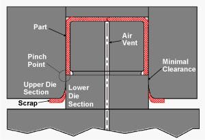
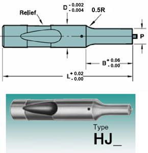
Figure 1
Pinch trimming die design

Various specialty metal cutting methods are used in stamping operations. Among them are pinch, breakout, and shimmy.

Pinch Trimming

Pinch trimming is a special method in which the vertical walls of a drawn or stretched vessel are cut by pinching the metal between two hardened tool steel die sections. In most cases, the clearance between the die sections is as little as possible (Figure 1).

Unlike a conventional metal cutting process, no shearing or fracturing takes place in pinch trimming. Items such as deep-drawn cans often are pinch trimmed.

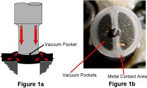
Although pinch trimming is a very popular method, because the metal basically is pinched off, a very sharp burr usually remains on the part (Figure 2). This burr must often be removed by tumbling the parts in a tub containing abrasives.

Figure 2
Result of pinch trimming

Pinch trimming also places a great load on the sides of the die sections, which results in high wear. Most pinch trimming operations require a great deal of maintenance.

Breakout Trimming

Breakout trimming is a specialty metal trimming process in which the metal is forced to fracture or break free from the vessel's flange. If you are accustomed to conventional cutting operations, this process most certainly may look harebrained to you. Unlike a conventional metal cutting process, the lower die section has a 45-degree angle ground on its edge. This angle has two basic functions: first, to allow the cup to fully nest in the lower die, and second,. to force the flange to bend upward slightly.

The cutting clearance also is much greater in breakout trimming than the clearance commonly used in conventional cutting operations. This additional clearance causes leverage action, but does not allow for the metal to be bent into a vertical wall. However rest assured, this process works well, especially for metals that severely work harden (Figure 3).

Figure 3
Break out trimming

Breakout trimming takes advantage of the metal's work hardening and reduced thickness in a given localized zone. This method works best for round or axial symmetrical drawn parts.

For breakout trimming to work effectively, the drawn cup must be properly prepared for the process. The inside radius on the cup's flange must be reduced to a dead sharp corner before using this method. This is achieved by drawing the cup deeper in the drawing operation or compressing it back over a dead sharp corner on the die section (Figure 4). Doing so reduces thickness in the radius and allows work hardening to take place.

Figure 4
Creating a small radius

After the cup has been prepared properly, it can be introduced into the breakout trimming process, in which the cup flange will be forced upward, causing the metal to breakat the dead sharp corner (Figure 5). Because the cup flange is round, as it is pushed upward it is forced into radial compression. This compression works to your advantage by forcing the cup to be fractured out of the flange.

Breakout trimming does not produce a burr as large as that produced by pinch trimming. Also, because the loads on the tool steel sections are minimal, the die requires less frequent maintenance. However keep in mind that this method can be used only in situations in which the metal must be cut at the intersection of the flange and the cup's vertical wall.

Figure 5

Shimmy Trimming

Shimmy trimming is a unique metal trimming process in which a series of specially designed cams are used to force the part to move side to side. Unlike conventional cam trimming, the part does not remain stationary, but rather moves horizontally in the die. It moves in such as fashion that it can be trimmed true to the surface of the vessel. Trimming 90 degrees or true to surfaceresults in a much cleaner cut and considerably lower burrs than pinch trimming.

A great advantage of shimmy dies is that they can cut the entire perimeter of a part in a single press stroke. Unlike conventional pinch trimming, a shimmy trimming operation is not restricted to straight line cuts. Features such as notches, curved cuts, as well as a various other cuts can be made. Many common items such as cigarette lighters and gun shells are made using the shimmy trimming process.

Figure 6
Parts trimmed with a shimmy trim die
Images courtesy of Vulcan Tool Corporation

Shimmy trimming operations also can be designed to cut metal as thick as 0.250 in. and, unlike conventional pinch trimming, can keep the original metal thickness in the trimmed area. Not like conventional cutting operations, shimmy dies require a pressure system such as a press cushion or a nitrogen gas manifold (Figure 6).

Which metal cutting operation a die design engineer chooses is based on many factors, including allowable burr height, parts volumes, metal type and thickness, and trim line geometry. No single trimming operation is best for all scenarios. The next article in this series will continue the discussion of metal cutting.

Die Basic Part 12

This article is one of a 16-part series on the fundamentals of stamping. Descriptions of all the articles in this series, and links to them, can be found at the end of this article.

Slug pulling, which occurs when scrap metal—the slug—sticks to the punch face upon withdrawal and comes out of the button, or lower matrix, is a serious problem that can damage parts and dies. Various methods can help reduce the occurrence of slug pulling.

Air Vents

Putting air vents in cutting and piercing sections most likely will not completely stop cutting slugs from pulling, but it's a good start. This is because trapped air that creates vacuum pockets is a major cause of slug pulling. It is good die-building practice to drill air vents in all cutting punches whenever possible, especially if they are piercing punches.

Spring Pins

spring pins

Figure 1
Spring Ejectors and Air VentsImages courtesy of Dayton Progress

A common, popular method for preventing slugs from pulling is to use a pierce punch with a spring-loaded ejector pin. However, this method is effective only if the punch is large enough to accept a spring pin.

The spring-loaded pin pushes slugs from the punch point and into the matrix. Keep in mind that to maximize the spring pin's effectiveness, it must be accompanied by an air vent. This can be achieved by drilling an oversized hole for the pin and allowing the trapped air to escape around the spring pin.

Spring pins work well in large dies containing large pierce punches, but they do not lend themselves well to small-die, high-speed operations. Many commercial punch manufactures can provide these types of punches for you. Some commercially available punches even have a special wire retainer that allows the maintenance technician to depress the spring pin, lock it in place with a special retention pin, and grind the punch with the spring depressed. This capability allows the punch to have the same amount of spring travel as a new punch (Figure 1).

Reduce the Punch-to-Die Clearance

Although reducing the cutting clearance shortens the life of the punch and matrix, it helps minimize slug pulling. This is because reducing cutting clearance forces the slug in compression during cutting. After the cutting is completed, the slug decompresses in the matrix for an interference fit.

For short-term runs and low-production parts, reducing the clearance may be your answer; however, for high-production dies, it is recommended that you use an engineered cutting clearance combined with an alternate method for slug retention.

Special Die Inserts, Buttons, and Matrix Alterations

Many commercially available inserts orbuttons can help address slug pulling problems. Some common commercial names are "slug huggers" or "slug-control buttons" (Figure 2).

Special die buttons

Figure 2
Commercial Slug Control Buttons

A slug-control button consists of two small slots machined at an angle in each side of the matrix. These slots cause a burr to be generated on the slug. The burr is forced downward at an angle, wedging the slug in the matrix.

A slug-hugger button has barbs in the matrix that impale themselves into the slug. Both of these methods work well and are highly recommended.

A reverse-tapered "bell mouth" button also works well. Most die buttons have a bell mouth taper machined into them, with the hole diameter increasing toward the bottom of the button. Although it may seem strange to use a button with a hole in the matrix that gets slightly smaller as it nears the clearance opening, this is an effective slug retention method. The reverse taper holds the slugs in compression in the matrix. Keep in mind that in most piercing operations, 0.0005 inch to 0.001 in. is more than sufficient taper. Too much taper and compression can cause the matrix to split (Figure 3).

Special die buttons figure 3

Figure 3
Alternate Slug Control Buttons

Vacuum Units

Commercially available vacuum units can be incorporated in your piercing operation. These units create a vacuum and pull the slug downward into the matrix. In a pinch, try a simple wet and dry vacuum. In my experience, it works fairly well. However, keep in mind that these vacuums typically are not meant to run for hours and hours. Even the higher-quality models burn up quickly.

Other Ideas

Although it may be somewhat crude, using a weld spatter technique on the inside of a button can be a relatively effective slug-pulling remedy. Commercially available deposit machines work best to execute this application. These special deposit machines deposit tiny barbs on the inside of the button. These barbs impale themselves into the slug and help prevent it from pulling upward.

These portable application machines have significant advantages over ordinary weld spatter. First, they can deposit tungsten or vanadium carbide on the button surface, which decreases button wear and increases slug-retention life. Second, the deposits can be made accurately with as little heat as possible. This helps to reduce tool steel and button damage. Deposit amounts can be carefully controlled.

Keep in mind that each cutting and piercing operation may require a different slug pulling method. The key is to remember that one pulled slug is one too many. Even a single pulled slug can result in extensive die damage. Don't risk ignoring the issue: An ounce of prevention is worth a pound of cure!

Die Basic Part 11

This article is one of a 16-part series on the fundamentals of stamping. Descriptions of all the articles in this series, and links to them, can be found at the end of this article.

Slug pulling is a serious problem in a stamping operation. Addressing the issue requires first understanding why the slugs are pulling.

What Is Slug Pulling?

When a pierce punch creates a hole, it also produces scrap, usually referred to as a slug. Slug pulling occurs when the slug sticks to the punch face upon withdrawal and comes out of the button, or lower matrix.

If a slug falls off the punch and onto the strip or part, it can damage the part and die. Keeping the slug down in the matrix or, better yet, completely pushing it out of the die is the desired scenario.

What Causes Slug Pulling?

Many factors contribute to slug pulling. Among them are trapped air; large cutting clearances; extremely fast piercing operations; sticky lubricants; improperly demagnetized punches; and fatigued or insufficient spring ejectors.

Slug pulling diagram

1. Trapped air/ vacuum pockets—The slug generated during the piercing process has some curvature. The curved, void areas where air is trapped, creating a vacuum action. During the perforating process, a tight seal is maintained around the punch perimeter. When the punch is withdrawn, this seal prevents the slug from coming off the punch (Figure 1a). Keep in mind that the only portion of the piercing punch that makes contact with the metal is a localized zone around the punch's outside diameter. Even punches with angularity make only localized contact with the metal (Figure 1b).

Trapped air must be allowed to escape to reduce the amount of vacuum. This is done by creating a small air vent in the center of the pierce punch, which allows the otherwise trapped air to exhaust itself from the vent hole and reduce the suction. Losing suction breaks the seal between the slug and the pierce punch and allows the slug to fall (Figure 2a).

Slug pulling diagram figure 2

When piercing punches that are too small to vent are used, other means of addressing slug pulling most likely will be necessary. Also keep in mind that addressing the trapped air probably won't solve the slug pulling issue completely, but it will certainly help.

2. Larger cutting clearances—Although using engineered or larger cutting clearances can result in much greater punch and matrix life, there is one drawback to doing so. As the clearance gets larger, compression on the slug decreases, which increases the chances of slug pulling.

When smaller cutting clearances are used during the perforating process, both the slug and metal outside the slug are forced into compression. After the slug is cut free, it decompresses and remains in the matrix. This is because the decompressed slug now has an interference or press fit into the matrix.

In simple terms, when greater cutting clearances are used, the slug will be slightly smaller than the hole in the matrix, which means it may be pulled from the matrix by the punch, resulting in slug pulling. Reducing the cutting clearance certainly can help this problem, but it also can shorten punch life and increase sharpening frequency. Rather than reducing the cutting clearance, it is recommended stampers try a few methods that will be discussed in the next part of this series (Figure 2b).

3. Oil / lubricant problems—Using heavy, thick, highly viscous oils and deep-drawing lubricants only adds to slug pulling problems. Unfortunately, these compounds often are necessary for forming dies to perform correctly.

Over time heavy oils and compounds can become coagulated and sticky. Thick, sticky compounds can cause slugs to stick to punches. Periodically cleaning the cutting components can help to resolve this sticky residue problem. Other methods to resolbe this problem will be discussed in Part XII.

Flat surface grinder

Figure 3
Using a flat surface grinder

4. Magnetized punches—Punches and die sections often are sharpened with a surface grinder. Most surface grinders secure the sections and punches to be ground by a high-power electro- or conventional magnet (Figure 3). Any ferrous metal that comes in contact with this magnet becomes slightly magnetized.

After the die components have been ground, they then must be demagnetized fully. This process is accomplished by using a commercially available demagnetizing unit. Magnetized pierce punches and die sections can cause slugs and other magnetic debris to be picked up and carried through the tool.

5. Weak or fatigued spring ejectors—Spring ejectors often are used in piercing and cutting punches. These small, spring-loaded pins push the slug from the punch face after cutting has taken place. If the spring behind the punch fails or fatigues, slug pulling can occur. Periodically inspecting and replacing springs is a necessary part of a good die maintenance program (Figure 4).

spring ejectors diagram

Figure 4
Spring Ejectors

Slug pulling can have disastrous consequences. A single slug carried through a progressive die can damage every tool in the station. The next part in this series will discuss methods for resolving slug pulling problems.

Die Basic Part 10

This article is one of a 16-part series on the fundamentals of stamping. Descriptions of all the articles in this series, and links to them, can be found at the end of this article.

Cutting is the most severe metalworking process that takes place in a die and shouldn't be taken lightly.

Cutting Basics

Cutting metal requires great force. For example, it takes approximately 78,000 lbs. of pressure to cut a 10-in.-diameter blank from 0.100-in.-thick mild steel. Consequently, the punch, die, and press must absorb overwhelming shock.

Overshocking the press and die components usually is what causes them to fail prematurely. If you work in a shop that blanks heavy metals, you know what I mean. You can hear and feel the press shock. Doing everything you can to reduce the unnecessary loading and shocking is important. Factors such as cutting clearance and shear angles contribute significantly to the amount of force required. They also affect the amount of shock that is generated.

Piercing Misconceptions

If you participated in a tool and die apprenticeship, you probably were taught the following rules for piercing punches:

  • The punch determines the hole size.
  • The cutting clearance always should be even (equal) around the punch.
  • 10 percent of the metal's thickness is a good cutting clearance for each side of the punch.

These are good starting guidelines for cutting, but they aren't entirely true. Let's examine each misconception.

The punch determines the hole size—Although the punch produces a hole that is very close to its actual diameter, altering the clearance between the punch and the button (sometimes referred to as the matrix) also affects the hole size. The simple truth is that a hole can be made slightly larger or smaller than the punch diameter by increasing or decreasing the cutting clearance. This is because of the way that the metal deforms before the cutting actually takes place.

Think of the metal that you're cutting as Silly Putty® or a rubbery plastic. If the clearance between the cutting punch and the button is insufficient, it will cause the metal to compress or bulge out away from the punch before the cutting takes place. After the slug is created, the metal grips the punch sides. This increased friction between the sides of the punch and the metal raises the amount of force necessary to strip or pull the punch from the metal.

The insufficient clearance between the punch and the button means that a greater force is needed to create the hole. Inadequate clearance also increases the load on the edges of the punch and the matrix, which causes premature edge breakdown.

After the punch is removed, the metal that once was compressed decompresses and collapses around the void area (the hole). The result is a hole that is smaller than the punch's diameter (Figure 1).


Figure 1
Insufficient Cutting Clearance

If the clearance between the punch and button is increased, the metal is pulled inward in slight tension into the button. After the slug is created, the metal pulls away from the edges of the punch, resulting in a hole that is slightly larger than the pierce punch.

Increasing the cutting clearance also reduces the cutting force needed to create the hole. In addition, because the hole is slightly larger than the punch, the force needed to strip the metal from the punch is greatly reduced (Figure 2).

Figure 2
Using Increased Cutting Clearance

Keep in mind that changing the clearance does not affect the hole size to a great extent—about 0.001 in. to 0.002 in. Although it might seem small, this change can reduce the friction generated during punch withdrawal significantly and extend the punch life.

The cutting clearance always should be equal around your punches—Once again, unless you are piercing only round holes, this statement is not entirely true.

Cutting clearances should change around the punch perimeter with respect to the punch geometry. Let me explain using this example: If you are piercing a square hole, you may notice that the corners of the punches are the first areas to break down. Once the corners break down, the entire punch must be sharpened. Ever wonder why the corners break down first? It's because this is the area that is subjected to the highest cutting loads. Very simply, wherever there is a small radial feature in a cut (nothing is worse than a dead sharp corner), the compressive forces will be greater.

Excessive compression can be compensated for by increasing the cutting clearance in areas with small radial features or sharp corners. Increasing the clearance in these areas helps to increase punch and button life and reduce the probability of a large corner burr. A good rule of thumb is to increase the clearance in the corners to approximately 1.5 times the normal clearance. An even better scenario is to avoid dead sharp corners whenever possible (Figure 3).

Figure 3
Increasing Cutting Clearances in Corners

10 percent of the metal's thickness is a good cutting clearance for each side of the punch—Once again, this statement isn't always true. While 10 percent is by far the most commonly used cutting clearance, it most certainly is not always the ideal cutting clearance.

Cutting clearances can range from as little as 0.5 percent up to as much as 25 percent of the metal's thickness per side. Among the many factors that determine the best cutting clearance are the metal's thickness and hardness and the punch size and geometry. For example, the ideal cutting clearance for piercing a 0.500-in.-diameter round hole in a sheet of 0.100-in.-thick 300 series stainless steel is about 13 percent of the metal's thickness per side, or 0.013 in. per side. This calculates to a total clearance of 0.026 in.

However, changing from a 0.500-in.-diameter punch to a 0.100-in.-diameter punch requires more cutting clearance, from 13 percent to 20 percent per side. This is because the smaller punch has a smaller radius, and compressive forces congregate at the smallest radial feature of a cut (just as in the rectangular punch example noted above).

Metal type also affects cutting clearance selection. Harder, higher-strength materials require more cutting clearance, while softer metals, such as aluminum, require smaller cutting clearances.

As you can see, metal cutting is slightly more complicated than often perceived. Understanding the many variables and how they affect the cutting process are key.

Die Basic Part 9

This article is one of a 16-part series on the fundamentals of stamping. Descriptions of all the articles in this series, and links to them, can be found at the end of this article.

Part VIII of this series discussed some of the specific mechanical properties of metals—ductility, elongation percentage, tensile and yield strength, and hardness—and how to derive these properties. This article describes other important mechanical properties, as well as a few behavioral characteristics.

Figure 1
Strain and Thickness Distribution

Strain

Strain can be defined simply as a measurable deformation of the metal. In other words, metal must be "strained" in order to change its shape. Strains can be positive (pulling the metal apart, or tension) or negative (pushing the metal together, or compression.) Strains also can be permanent (plastic) or recoverable (elastic). The result of elastic straining commonly is referred to as springback, or elastic recovery.

Remember, every metal type wants to return to its original shape when it's deformed. The amount the metal springs back is a function of its mechanical properties. When engineers refer to part areas that are "high strain," they typically are referring to areas that have been subjected to substantial stretch or compression. Figure 1shows a simulation image of a part that has been stretched. Each color represents a different type and amount of strain. Some of the strains are positive and others are negative.

Stress

Stress is simply the result of straining the metal. When subjected to stress, metal incurs internal changes that cause it to spring back or deform nonuniformly. Trapped stresses within a part often result in a loss of flatness or other geometric characteristics. All cut or formed parts incur stress.

Stretch Distribution

Figure 2
Stretch Distribution / Tensile Test

Stretch distribution is a very important mechanical property. A metal's stretch distribution characteristics control how much surface area of the stretched metal is permanently deformed. Stretch distribution is determined primarily by checking the metal's thickness when it's deformed in tension during the tensile testing process. The more uniform the thickness distribution, the better the stretch distribution. Stretch distribution also is partially expressed in the metal's n value. Figure 2 shows different stretch distribution results. The red areas of the sample test coupon represent areas that have been stretched.

n Value

To understand n value, otherwise known as the work or strain hardening exponent, you must understand that every time metal is exposed to permanent deformation, work hardening occurs. It's the same thing that happens when you bend a coat hanger back and forth. As you bend the hanger, it gets harder and harder to bend. It also becomes more difficult to bend it in the same place. This increase in strength is the result of work or strain hardening. However, if you continue to bend the hanger in the same spot, it will eventually fail.

Ironic as it may seem, materials need to work-harden to achieve both good stretchability and stretch distribution. How they work-harden is the key. The n value of a material can be defined fundamentally as the metal's stretchability; however, it also is an expression of a material's stretch distribution characteristics.

Perhaps one of the most important mechanical properties to consider if the stamped part requires a great deal of stretch, the n value is expressed numerically in numbers from 0.100 to 0.300 and usually is carried out two or three decimal places. The higher the number, the greater the metal's stretchability and stretch distribution. Higher-strength metals, such as spring steel, have very low n values, while metals such as those used for making oil pans and other deep-formed parts usually exhibit higher n values.

The metal's n value also is a key mechanical value used in creating forming limit diagrams. (This will be discussed in subsequent parts of this series.)

r Value

The metal's r value is defined metallurgically as the plastic strain ratio. To understand this concept, you must clearly know the difference between stretching and drawing. Stretching is a metal forming process in which the metal is forced into tension. This results in an increase in surface area. Items such as most automobile hoods and fenders are made using this process.

Drawing is the displacement of metal into a cavity or over a punch by means of plastic flow or feeding the metal. Items such as large cans, oil pans, and deep-formed parts usually are made using this process.

Figure 3
Plastic Strain Ratio r Value

The metal's r value can be defined simply as the metal's ability to flow. It also is expressed numerically using a value from 1 to 2, which usually is carried out two decimal places. The greater the r value, the more drawable the metal (Figure 3).

The metal's r value is not uniform throughout the sheet. Most metals have different r values with respect to the metal's rolling direction. Testing for a metal's r value requires tensile testing in three different directions—with the rolling direction, against the rolling direction, and at 45 degrees to the rolling direction. The test results usually are averaged and expressed as the r bar, or average of the r values.

Figure 4
Earring Caused by Differences in the Metal's r Value

Differences in the plastic strain ratio result in earring of the metal when being drawn. For example, when drawing a round shell from a round blank, the results will be a near square bottom on the flange of the cup. This effect (Figure 4) is caused by different amounts of metal flow with respect to the metal's

Surface Topography

A metal's surface topography, defined simply as the metal surface finish, is created mainly during the metal rolling process. Surface topography is an important metal characteristic. When being drawn, metals often require a surface finish that has the ability to hold lubricant. Surface topography is determined with a measuring tool called a profilometer.

This wraps up the discussion of sheet metal characteristics. The next article in this series will focus on metal cutting.

Die Basic Part 8

This article is one of a 16-part series on the fundamentals of stamping. Descriptions of all the articles in this series, and links to them, can be found at the end of this article.

Figure 1

Part VII of this series introduced two basic types of metals used to manufacture stamped parts—ferrous, metals that contain iron, and nonferrous, metals that do not contain iron. This article discusses the specific mechanical properties of these metals in more detail.

The metal's mechanical properties greatly influence the process chosen to transform the flat sheet metal into the finished part's shape and profile. The mechanical properties often influence the tool steel and lubricants used to form and cut the sheet metal. They also determine if offline processes, such as annealing or hardening, are necessary.

Literally thousand of metals are used in stamping today, and it would be nearly impossible to cover each material's specific mechanical properties. This article explains the fundamental properties they all share and discusses methods for testing and defining some of these properties.

Tensile Testing

Among the numerous methods used to test metal's mechanical capabilities, the most widely used and accepted is the tensile test. In a tensile test the metal is carefully cut to a specific shape according to a given testing standard. The cut sample is called the test coupon.

The test coupon then is placed into a special machine called a tensile tester, which grabs each end of the coupon and stretches it. The metal is stretched until it fails (breaks). Factors such as how much the metal stretched, how it thinned out, how it changed shape, and how much force was required throughout the entire forming process are carefully measured and documented. Mechanical properties such as elongation percentage, tensile strength, yield strength and nandr valuescan be obtained using this test (Figure 1).

The tensile test also can generate a special graph called a stress/strain diagram (Figure 2). This diagram shows the relationship between the force that is needed and the deformation that occurs. In short, it shows how the metal behaves when being deformed.

Ductility

Figure 2

Ductility is a very broad term that describes a metal's ability to change shape without fracture. In flat-rolled steel, ductility usually is measured by hardness or mechanical properties in a tensile test. Generally speaking, the more ductile the metal is, the more it can be deformed. However, keep in mind that metal can be deformed in more than one way. Better defining how ductility affects the forming process requires first defining a few important properties that are obtained when the metal is subjected to a tensile test.

Elongation Percentage. Elongation percentage is one of the properties that affect metal ductility. Elongation can be described simply as a numerical expression of how much the metal stretched within a given boundary. The most commonly used boundary is 2 inches.

The metallurgical definition and mathematical equation for elongation can be expressed as the extension of a uniform section of a specimen expressed as a percentage of the original gauge length:

Elongation, % = (Lx- Lo) / Lox 100,
where Lois the original gauge length and Lxis the final gauge length.

For example, a material having 42 percent total elongation stretched 42 percent of its beginning length within a 2-in. boundary before it fractured.

Tensile Strength. Tensile strength can be defined as the maximum stress that a material can withstand. In tensile testing, the measurement is the ratio of maximum load to the original cross-sectional area. Often it is also referred to as the metal's ultimate tensile strength (UTS).

Another definition of tensile strength is the maximum stretching that a material is capable of withstanding without breaking under a gradually and uniformly applied load. Simply, it is the measurement of the breaking or rupturing force.

Yield Strength. A metallurgist may describe yield strength as the point at which material exhibits a determined deviation from the proportionality of stress to strain. While this most certainly is a true statement, it is not one that's easy to understand. Think of yield strength as the measurement of the force necessary to deform the material permanently.

Remember, before a material can permanently change its shape, it must first go through a transition from elastic deformation (not permanent) to plastic deformation (permanent). Think of it like this: Imagine suspending a flat piece of sheet metal that is 0.062 in. thick, 12 in. wide, and 24 in. long between your arms. The sheer weight of the metal will cause it to sag slightly in the center. This change in shape is the result of elastic deformation, meaning that although you have witnessed a change in the metal's shape, the change is not permanent. This can be proven by placing the metal on a flat table, at which point it will return back to a flat sheet.

Figure 3

However, if you severely bow the metal sample and apply enough force, it will begin to take the shape of the bow. The point at which the metal permanently changes its shape is its yield point. Yield strength is a measurement of how much force it took to get the material to deform permanently, give up, or "yield." Yield strength usually is expressed in pounds per square inch (PSI), or megapascals.

Hardness. Hardness, which can be defined simply as a measurement of the metal's penetrability, usually is tested with a special machine. The most common hardness testing machine is a Rockwell/Brinell tester (Figure 3). This device applies a load or weight to a point that penetrates into the steel's surface. The deeper the penetration, the softer the material. By measuring the applied force and the penetration depth, we can obtain a numerical value that expresses the metal's hardness.

Although hardness alone does not give enough data to determine the metal's formability, it can be used for comparative analyses. Generally, with the exception of metals such as aluminum, the softer the metal, the more ductile it will be. Materials such a copper, brass, gold, titanium, and many other nonferrous metals often are categorized by their hardness.

This article discussed only a few mechanical properties that both ferrous and nonferrous metals have. The next article in this series will cover even more properties.

Die Basic Part 7

This article is one of a 16-part series on the fundamentals of stamping. Descriptions of all the articles in this series, and links to them, can be found at the end of this article.

Previous articles in this series focused on stamping dies and production methods. This article discusses stamping materials—both ferrous and nonferrous.

To process, design, and build a successful stamping die, it is necessary to fully understand the behavioral characteristics of the specific material to be cut and formed. For example, if you are forming 5000 series aluminum and you follow the same process you use for deep drawing steel, the operation most likely will fail—not because aluminum is bad, it's just different from steel.

Each metal has its own unique mechanical characteristics. The metal type that the die is forming and cutting often determines the tool steel that must be used, as well as how many operations are required. In addition, different metal types require different lubricants, press speeds, and capacities. Because stampers are end users of metals, this article focuses on selecting and understanding the end-product behavior only and not the metal-making process.

Two Metal Types

Although there are literally thousands of metals that can be stamped, all fall within two basic categories—ferrous and nonferrous. Ferrous metals contain iron, and nonferrous metals are those without iron. Steel is a classic ferrous metal because it is derived essentially from iron ore. Aluminum, however, contains no iron and is classified as a nonferrous metal.

With the exception of a few exotic specialty metals, ferrous metals are magnetic and nonferrous metals are nonmagnetic. Because nonferrous metals do not contain iron, they are less likely to deteriorate through oxidation or rusting. Some commonly stamped nonferrous metals are aluminum, brass, bronze, gold, silver, tin, and copper.

Aluminum is a very popular metal for applications in which strength, weight, and corrosion resistance are factors. Aluminum is approximately one-third the weight of steel. Although hundreds of alloyed steels exist, plain carbon steel is by far the most commonly stamped ferrous metal.

Steel Basics

Carbon is a basic element of the steelmaking process. In its raw form, carbon could be described as a chunk of coal or pencil lead. A piece of coal buried a mile or so beneath the surface of the earth and subjected to intense heat and pressure for about a thousand years yields what? A diamond. A diamond is nothing more than pure, compressed carbon. (Yes, "Carbon is a girl's best friend." Just make sure that it's natural, highly compressed carbon that you are giving her.)

From this basic knowledge of carbon, it is easy to deduce that the more carbon present in the steel, typically the stronger and less formable it will be. For example, tool steel used in manufacturing dies contains far more carbon than the sheet metal being processed. Keep in mind that the carbon content of a particular metal does not fully determine the metal's mechanical properties. Carbon content is only one factor.

Figure 1

Alloys

An alloy is a homogeneous compound or mixture of two or more metals that enhances the metal's chemical, mechanical, or physical properties. When combined, the metals must be compatible and resist separation under normal conditions. For example, two common alloys added to steel are chrome and nickel. Chrome is very hard and resists oxidation, and so does nickel. Adding chrome and nickel to steel produces stainless steel. These added alloys enable the stainless steel to resist oxidation.

If you have purchased stainless steel flatware recently, you may have noticed different grades are available. These grades usually are designated as good, better, and best. The main difference in the quality depends primarily on the alloy content. The numbers that you see on the packaging, such as 18/8 or 18/10, refer to the percentage of chromium (18 percent) and nickel (8 percent or 10 percent) in the stainless steel. Chromium is known for its stain resistance, and nickel is known for its high luster and shine. Higher alloy numbers mean higher quality and cost.

Alloys can be introduced into both ferrous and nonferrous metals. Many aluminum alloys are available today. A very common steel type used in the automotive industry is high-strength, low-alloy steel (HSLA). Alloys are combined with medium carbon steel to give the metal good load-carrying ability and reasonable formability. These mechanical properties make HSLA a good candidate for frame rails and other automotive structural parts that require strength.

Figure 2

The number of alloyed metals used in stamping are far too numerous to mention in this article. The thing to remember is that alloyed metals are a combination or mixture of two or more metals that create a new metal with special characteristics.

Plain Carbon Steel

Plain carbon steel can be defined as pure steel, meaning that it contains no intentionally added alloys. Plain carbon steel—among the most popular steel types used in stamping today—usually is assigned a four-digit number, such as 1006, 1020, 1050, and 1080. To determine the steel's carbon content, simply place an imaginary decimal place between the four digits and read the last two digits as a percentage of 1 percent. For example, 1010 steel contains 10 1/100 of 1 percent carbon, or 0.10 carbon (see Figure 1).

The more carbon in the steel, the harder it will be to cut and form. Metals with increased carbon can be hardened further by heating them to a critical temperature and cooling them quickly in the proper quenching medium. Processing harder metals requires dies made from tougher, more wear-resistant tool steels. Also, greater force is needed to cut and form the metal. Knowing the metal's carbon content can help you make a better decision about the appropriate tool steel and press capacity. Figure 2 shows a few typical applications with respect to the steel's carbon content.

This article covered very basic metal types and properties only. The next article in this series will discuss the mechanical characteristics of different metals in more detail. It also will explain how the metal selection affects the die processing method and die materials.