


*. YamaHa BysOn


 In any press tool design, the first thing to consider is how to determine the flat blank length of the folded component. I won’t go into the boring theory of how the material behaves during bending and how the individual material property affects the length and spring back. To be frank, I hate all these theories!
During the bending process, the material being bent results in forces: tension and compression. The external portion of the sheet will undergo tension and stretch to a greater length, while the internal portion experiences compression and shortens. The neutral axis is the boundary line inside the sheet metal, along which no tension or compression forces are present. As a result, the length of this axis remains constant. This is the bend allowance that we are interested to know to determine the flat blank length.
There are tones of materials and formulas out there in the cyberspace teaching people how to make calculations. I personally did not use any of these formulas’ during my last thirty years of tool making career.
I applied only one formula for any flat blank length calculation.
@ Pi D/360
where D= circumference of neutral line
@ = Bend angle
Any radius bend smaller than 2x the material thickness, the neutral line will be 1/3 thickness
Any bend radius equal or larger than 2x material thickness, the neutral line will be = 1/2 material thickness.
90 degree sharp bend radius.= 0.4 x material thickness.
+/- 0.05 mm accuracy can be achieved by applying the above method. Of cause, the bending clearances and accuracy of the bend radius does affect the end result.
All metal has a certain degree of spring back after its being bent. During sheet metal bending, the interior radius of the bent metal is under compression and the exterior bend radius is in tension and stretched. Due to the metals’ elasticity, it tends to go back to its original shape after its being bent and this is know as spring back. All metals, when subjected to deformation, exhibit a certain amount of elastic recovery. The amount of spring back in sheet metal bending depends on the following factors.
Factors affecting spring back in sheet metal bending.
In metal stamping, bend angle will never able to get it perfect every time, a press tool can be designed and built to make acceptable bend angles though it will never be perfectly consistent.
There are many different methods adopted by different tool makers to overcome the spring back in sheet metal bending. The key is how to make it easily, quickly, safely while making adjustment within the press while having the ability to compensate minor differences in coil thickness and mechanical properties at the same time.
Overcoming spring back in progressive tool
I tried many methods in the past. Such as coining the external bend radius, over bend the angle, reduce bending clearance etc. All these can’t really provide an effective solution to it until I tried the following method which I’m happily using for almost all the high speed progressive tools in my design.

In Fig 1. Let’s say you are bending a 1.0 mm thick steel sheet with a R 2.0 internal bend radius. The length of the neutral line is 3.927 mm. Refer to flat blank length for how to compute the neutral line.

In Fig 2. A 45 degree pre-bend is to be placed before the 90 degree bend, the bending is suppose to start from the 1.9635 calculated position. ( length of the 45 degree art ) To overcome the spring back, the location has to move away by 0.05 mm. See Fig. 2a.

In Fig 3. A 90 degree bend as usual. Due to the off-set start line, the bent angle will be at near 90 degree or lesser after the metal springs back.

Fig 4. Showing the design of an adjustable side cam to fine tune the bent angle for any minor differences in thickness and properties.
Some readers wrote to me after reading my previous post on “Metal forming spring back”. The technique I mentioned in the post was used on a progressive tool it is not suitable in the single forming tool.
Some of the factors for successful bending are the size of interior bend radius and the metal grain direction or direction of rolling. In general, the interior bend radius should be minimum a metal thickness. Good way bend has more spring back than the bad way.
The most common technique to control the metal spring back is by setting or coining the outer radius of the bent metal by a punch. The punch radius must be machined to the metal radius plus 0.07mm to 0.012mm to ensure full metal contact at the outer radius. We can compute the size by using exterior Radius x 4/3. (See Fig. 1)

There are also some toolmakers that make the die insert slightly smaller than the bend width to avoid cutting burr interfere with the form to control the spring back of the metal.
Another alternative method is to machine a 45% angle at the punch face, allowing adjustment to the 90-degree bend. The punch can be adjusted downward to further collect the bend angle. Drawback of this method is that it might produce a flat dent across the bend metal and it may not be acceptable. ( Fig. 2)

For “U” shape bending, the punch is machined with a recess at both sides of the edges of the punch. The depth of the recess is about 10% of the material thickness, the recess coin into the material thickness to overcome the plastic deformation of the metal, thus, spring back can be controlled. (Fig. 3)

For sharp edge bending, a coin line can be machined along the bend lines. The depth of the coin line is about 0.3 of the metal thickness. (Fig. 4) This technique produces an accurate and level flange, especially so in short edge bending. Furthermore, this technique requires lesser force to make the bend.

This article is one of a 16-part series on the fundamentals of stamping. Descriptions of all the articles in this series, and links to them, can be found at the end of this article.
Part XVI of this series wrapped up the discussion of bending in stamping operations. This article focuses on drawing.
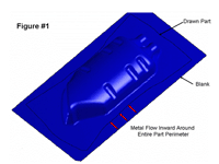
Figure 1
Click image to view larger
Drawing is a metal forming process in which a product is made by controlling sheet metal flow into a cavity and over a punch. The process of deep drawing means that the part must be taller than its minimum width.
Many people confuse drawing with stretching. True drawing results in very little stretching of the metal. Drawing requires metal flow, while stretching does not. It is only through the drawing process that objects such as oil pans, beer kegs, and oil filters can be made.
Drawing can be better defined as the process of displacing pre-existing surface into an alternate-shaped vessel containing nearly the same surface area. Stretching can be defined as the increase of surface area that results in a product with more surface area than the original surface area.
Drawing requires the metal to feed inward toward the punch. Very little or no metal flow takes place during stretching. However, keep in mind that because drawing does require tension to pull the metal inward, some stretching occurs during drawing.
The key in deep drawing is to limit the amount of metal stretching and thinning that take place. Items such as oil pans require significant drawing and stretching. Achieving a deep-drawn product that exhibits very little metal thinning requires extensive knowledge of sheet metal properties, drawing ratios, radii, and friction.Figure 1 shows the drawing process.
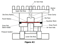
Figure 2
Click image to view larger
the deep-drawing process is not directional-specific. in other words, the direction in which the drawing takes place really doesn't matter. you can draw a part up or down into a cavity. you can even draw a part vertically using cams or special vertical-motion presses.
please keep in mind that i am in no way indicating that process engineers or die designers don't pay close attention to the direction in which are drawing. drawing direction must be given careful attention because it affects the ability to move, cut, and eject the part in the die. if drawing is incorporated into a progressive die, the drawing direction also may affect the die and strip carrier design.
Figure 2 shows a section view of a very simple single-action drawing die. this die is designed to produce a round cup with a small flange. a basic drawing die consists of the following components:
1. Die set or foundation. This could be made of mild steel cast iron or aluminum. It serves as the guided foundation on which all of the metal forming sections will be mounted.
2. Draw cavity. The draw cavity represents the drawing die's female portion. Uually made from tool steel or solid carbide, it serves as the cavity in which the metal is formed.
3. Ejectors and knockouts. These pressure-loaded components serve to push or eject the part from the draw cavity. a high-pressure knockout must be timed properly so that it pushes the part out of the cavity after the die has fully separated. If the knockout is timed incorrectly, the part can be crushed during the return stroke of the press.
An alternate method to using a knockout is to use a small ejector pin and a lightweight spring. this spring must have enough force to eject the part adequately but not deform it during the press's return stroke. The pin and spring method does not require specific timing. However, keep in mind that certain part geometries require a great deal of force to eject from the cavity. in such cases, a timed high-pressure knockout may be necessary.
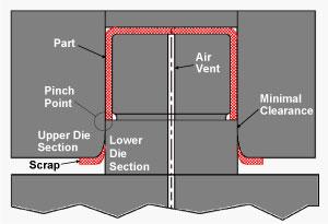
4. Air vents. Air can be trapped during drawing. This trapped air must be vented out of the tool. Not venting the air can cause defective parts, splitting, and wrinkling, as well as make it difficult to strip the drawn part from the cavity.
It is critical that both the cavity and punch contain air vents. Air vents in the cavity allow trapped air to escape during the downstroke of the press; air vents in the punch allow air to be pulled into the punch, which prevents suction during the part-stripping process.
5. Die face. The die face is the surface surrounding the cavity. it can be a flat or a contoured surface. this surface interfaces with the sheet metal and keeps it from wrinkling during the drawing process. the die face typically is made of tool steel or carbide and is highly polished in the direction of metal flow.
6. Draw punch. This component represents the male shape of the drawn part geometry. Like the cavity, it usually is made of tool steel. In most cases, it is polished to a mirrorlike surface. However, there are times when a rough surface is desired.
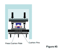
Figure 3
Click image to view larger
7. Blank holder /draw pad / binder. This pressure-loaded plate, which serves to keep the metal from wrinkling during the drawing process, typically is loaded with gas springs. However, certain drawing dies can achieve the force needed to control metal flow through the use of a press cushion.
8. Pressure system. The pressure system supplies the force necessary to control metal flow. It may consist of gas, coil, hydraulic, or urethane springs. Certain drawing dies utilize a press cushion to obtain the needed pressure. A press cushion is a plate or series of vertically moving thick, flat plates mounted beneath the press's bolster plate. These plates transfer the force to the bottom of the draw pad using a cushion pin (Figure 3).
9. Equalizer block. This block functions to maintain a specific gap between the die face and the draw pad surface. It also allows for minor adjustments to be made with respect to how much pressure is being applied to the blank.
This article is one of a 16-part series on the fundamentals of stamping. Descriptions of all the articles in this series, and links to them, can be found at the end of this article.
Part XV of this series described several bending methods—wipe, coin, relief, pivot, and V. It also discussed springback and how to compensate for it when using these methods. This article focuses on other bending processes. Keep in mind that the key to success is to design the bending process so that it can be easily, quickly, and safely adjusted to allow for material variables.
Rotary bending perhaps is one of the most popular and effective ways of creating a precision bend. Rotary benders, also know commercially as Ready Benders® or Accu-Bend™ benders, have many advantages over conventional wipe bending methods. First, let's examine how they work.
Rotary or rocker benders consist of a foundation block, often referred to as the saddle. The saddle has a spring-loaded V-shape component called the rocker. This rocker rotates about its centerline and performs the bending action. It acts as both a holding pad and the bending mechanism.
Although this type of bender can be installed in almost any direction with respect to the ram travel, it most commonly is fastened to the upper die shoe. As the bender moves down, the rocker makes contact with the sheet metal. One contact point acts as a holding pad, while the opposite contact point rotates, creating the bending action. After the bend is completed and on the press's return stroke, the spring forces the rocker to return back to its original or idle position (Figure 1).

Figure 1
Advantages. Rotary bending has some advantages over other methods. The most advantageous feature is the simplicity of adjustment. Changes in the bend angle can be made simply by shimming or grinding the height of the assembly. Doing so takes very little time, and time is money.
Rotary benders can bend as much as 120 degrees and are well-suited to bending high-strength material. One company in Sweden has successfully created two 90-degree return bends in steel with yield strength of 980 mega pascals. This translates into steel that by U.S. standards has a yield strength of more than 142,000 pounds per square inch (PSI)—five times stronger than low-carbon steel. Attempting to make such a bend in a conventional wipe-bending operation most certainly would be impossible.
Another advantage is that, unlike conventional wipe bending, rotary benders require much lower forces to create the bend. Anywhere from a 40 percent to 80 percent reduction in force can be expected. This makes this method ideal for producing long, heavy-gauge, large parts, such as truck and semi frame rails.
You can expect less hole distortion in rotary bending. Consider a hole that is pierced in a flat blank and later bent into a vertical wall. During conventional bending, this hole can be subjected to a great deal of tension, which causes the hole to distort. Because rocker benders fold the metal around the punch, hole distortion is eliminated (Figure 2).
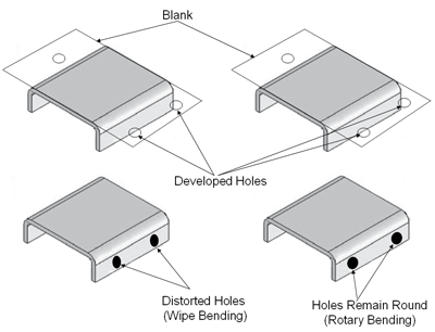
Figure 2
Inserting rockers with a special hard plastic called Delrin® can make them nonmarking, which is desirable when bending cosmetic-quality stainless steel or prepainted materials.
Rotary benders can used to bend up or down. They also can be placed on cam slides.
Disadvantages. Despite the many advantages, rotary benders do have some disadvantages. First, they can be quite expensive; however, consider the advantages of the reduction in downtime and frustration. Overall, they often pay for themselves in a short period of time.
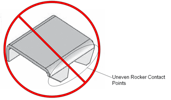
Figure 3
Poor Candidate for Rotary Bending
Also consider that you most likely will not need an external pad, which reduces die cost. Often the true cost of designing and building a conventional wipe bending die is much greater than the rocker bender. Don't confuse cost with value. In my opinion, rotary benders are worth every penny.
Because these benders have moving parts, there is a risk of galling up and failing to rotate. This can be prevented by periodicallycleaning and lubricating them.
Remember that rotary benders can be used for straight-line bending only. Avoid using them to bend special-shaped trim lines that do not allow for simultaneous punch contact. Angled corners are not good candidates for rocker benders (Figure 3).
Overall, I highly recommend using rotary benders for appropriate applications. They are available commercially from a few reputable suppliers.
Reverse U bending is a unique but effective way of obtaining either a 90-degree bend or a bend with a slight negative angle. This process utilizes a high-pressure pad with an insert that can be adjusted in height by shimming or grinding it. The insert causes the part to bow upward in the center of the punch where a void has been created. Raising or lowering the insert changes the severity of the bow. Keep in mind that this bow must be created with the pressure exerted by the pad. This often requires the use of high-pressure gas springs.
After the bow has been created, the pad moves downward and the bends are established. Upon punch removal, the part has a tendency to spring back in the center, which causes the bends to "toe in." This method works well with materials that exhibit a great deal of springback. If the metal permanently deforms in the center bowed area, it may be necessary to push the part back flat in order to achieve a 90-degree angle (Figure 4).
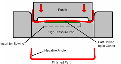
Figure 4
Reverse U Bending Process
Remember that the true key to bending success is to design the tool in such a fashion that it can be quickly, safely, and accurately adjusted with respect to ever-changing incoming variables. Avoid using the grinding and welding process whenever possible.
This article is one of a 16-part series on the fundamentals of stamping. Descriptions of all the articles in this series, and links to them, can be found at the end of this article.
Part II of this series presented a basic overview of metal forming operations, such as bending, flanging, drawing, ironing, coining, curling, hemming, and embossing. This and future installments discuss these operations in more detail. We will look at factors controlling the success of each operation, as well as tooling design guidelines. Let's begin with metal bending, a process often perceived as the simplest.
Bending can be defined simply as a forming operation in which the metal is deformed along a straight axis. Both compression and tension occur when bending sheet metal. The inside radius of the bent metal is in compression, or being squeezed together. The outside bend radius is in tension, or being stretched.
Because of the metal's elastic properties, it wants to decompress on the inside radius and return to its flat shape on the outside radius (Figure 1), which causes springback. Also know as elastic recovery, springback is present in all metal bending operations.
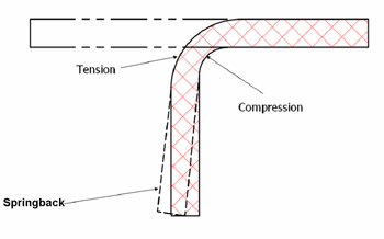
Figure 1
For a 90-degree bend angle, the metal must be bent to an acute angle (less than 90 degrees) and allowed to spring back to its finished position, a difficult task given the fact that a press ram typically travels vertically only. In addition, because of natural mechanical variability in the material from coil to coil and from the beginning of the coil to its end, attempting to achieve a consistent, precision angularity in a bending operation can be very difficult.
If ultraprecision bend angles are required, one of the best things you can do to achieve them is to design the tool so that it can be adjusted quickly, safely, and effectively to compensate for incoming variables.; Changing the product design also can help reduce springback and inconsistency problems. Incorporating darts, ribs, or gussets into the part design will enhance stiffness and reduce the amount of springback (Figure 2).
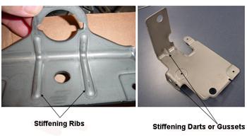
Figure 2
Photos courtesy of Batesville Tool and Die Company.
Several basic types of bending methods can be incorporated into a stamping operation—wipe bending, V bending, and rotary bending. All three are popular, and each has its advantages and disadvantages.
Wipe Bending—One of the most common methods used, but not always the most effective, is simple wipe bending. Unfortunately, this method does not allow for much overbending other than the very slight acute angle that can be achieved by wiping the side extremely tight (Figure 3). Even though wipe bending effectively creates a bend, controlling the bend angle is very difficult. This method is not well-suited to bending high-strength metals or for parts requiring precision bend angle tolerances. Wipe bending can be improved by capturing the outside profile of the radius with the forming die section.
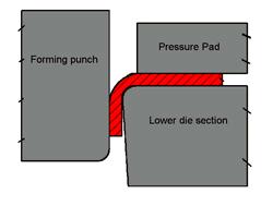
Figure 3
Simple wipe bending method
Figure 4shows a coin relief method. This process allows the outside radius to be coined, or squeezed, near the lower tangent point, which causes under- or over -bending to take place. The coin relief method works best when the metal is bent over a radius that is equal to or less than one metal thickness, and the metal is not ultrahigh-strength. One advantage to this method is that by vertically shimming the forming section up and down, the gap, as well as the amount of coining, can be adjusted. This allows for easy adjustments to be made for variability in the metal's thickness and mechanical properties.
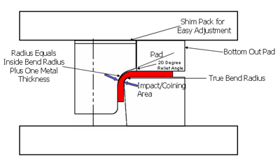
Figure 4
Coin relief bending method
Figure 5shows a pivot-style bending method, which incorporates both wipe bending and cam motion. This design works well both to create the bend and to adjust the amount of overbend. Overbend is created by adjusting the lower driver block vertically up and down.
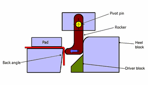
Figure 5
Pivot style bending design
V Bending—A very good method for obtaining a given bend angle, V bending is undoubtedly the most common method used with press brake bending. An acute angle ground on both the punch and die can provide adequate overbending of the metal. Also, the bending amount can be altered by adjusting the amount of coining the metal undergoes at the bottom of the press stroke (Figure 6).
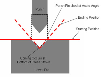
Figure 6
V bending method
One disadvantage to V bending is that it often requires the part to be rotated in such a manner that sometimes is difficult to incorporate in a progressive die. An advantage is that it often requires less force to create the bend compared with conventional wipe bending.
This article is one of a 16-part series on the fundamentals of stamping. Descriptions of all the articles in this series, and links to them, can be found at the end of this article.
Although fineblanking and GRIPflow® often are categorized as metal cutting operations, they more closely resemble a cold metal extrusion process that creates what appears to be a blanked part. The processes can be defined simply as methods in which a part is squeezedfrom the strip.
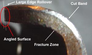
Figure 1
Results of Conventional Cutting
Unlike parts made with conventional metal cutting methods, the parts made using fineblanking and GRIPflow have little or no fracture zone (Figure 1). In other words, these parts appear to have smooth, square machined edges.
These processes also can produce parts with very close flatness and dimensional tolerances and roughness of about 2 to 3 �m, which means that, in many cases, postprocessing operations such as grinding and milling can be eliminated.
Parts commonly made using fineblanking and GRIPflow include gears and parts that require close flatness tolerances or a square cut edge. These processes also can pierce holes with diameters as small as one-third of the metal's thickness and very close to the part's edge.
Before these methods were available, the metal had to be shaved in one or several shaving operations to achieve a smooth cut edge. Shaving in a die often produces slivers and debris that can create tool problems and product defects.
Invented in Switzerland in the 1920s, fineblanking, unlike conventional stamping methods, utilizes a special triple-action hydraulic press called a fineblanking press. Fineblanking requires the use of extreme-pressure pads. These high-pressure pads hold the metal flat during the cutting process and keep the metal from plastically deforming during punch entry.
In fineblanking presses, a V-ring is incorporated into one of the high-pressure pads. This V-ring also is commonly referred to as a stinger or impingement ring.
Before the punch contacts the part, the V-ring impales the metal. It surrounds the part perimeter and functions both to trap the metal from moving outward and push the metal inward toward the punch. This action reduces the rollover that occurs at the part's cut edge. Using high-pressure pads combined with the stinger ring and close clearances keeps the metal from fracturing and creates a smooth edge (Figure 2). Because the part is held extremely tight between the high-pressure pads during cutting, part distortion is minimal.
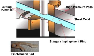
Figure 2
Fineblanking Process
Unlike conventional cutting operations that use approximately 10 percent of the metal's thickness for the cutting clearance, fineblanking operations usually use clearances less than 0.0005 in. per side. This small-clearance requirement combined with high pressure also contributes to the fully sheared part edge.
Once again, don't confuse fineblanking with a cutting operation. It's not a cutting operation at all; it is more like a cold extruding process. The slug (part) is pushed or extruded from strip held so tightly between high-pressure holding plates and pads that the metal cannot bulge or plastically deform during the process. These high-pressure pads fit precisely around all cutting components. Fineblanking can be used to produce parts as thick as 0.5 in. from a variety of metals.
Not to be confused with fineblanking, the GRIPflow process does not use a stinger or impingement ring to stop outward metal movement but relies solely on hydraulically applied pressure to the blank. The pressure is applied through precision-guided pressure pads.
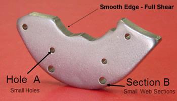
Figure 3
GRIPflow Part Source: Ebway Corp.
Think of the GRIPflow process as similar to compound blanking. However, unlike a compound blanking operation, GRIPflow uses very small cutting clearances between each of the cutting components. This small clearance, combined with high blank holding pressures and precision clearances between all moving components, produces a smooth-edged part that can be held to very tight dimensional tolerances (Figure 3).
Once again, keep in mind that GRIPflow is not a metal cutting process but a cold extruding process. The cutting sections do not have cutting shear ground on them.
It is difficult to tell the difference between a part that was fineblanked and one made using the GRIPflow process just by looking at them. Unlike fineblanking, GRIPflow does not require a triple-action press. Because it uses hydraulic cylinders mounted in the die, the process is best-suited to a hydraulic action press.
Both fineblanking and the GRIPflow process now are being used to produce many parts previously made by more costly processes, such as casting, forging, and machining. Because other minor forming operations can be combined with these special processes, they both lend themselves to many geometries. Keep in mind that each process has its own advantages and disadvantages.
This article is one of a 16-part series on the fundamentals of stamping. Descriptions of all the articles in this series, and links to them, can be found at the end of this article.
Although fineblanking and GRIPflow® often are categorized as metal cutting operations, they more closely resemble a cold metal extrusion process that creates what appears to be a blanked part. The processes can be defined simply as methods in which a part is squeezedfrom the strip.
Figure 1
Results of Conventional Cutting
Unlike parts made with conventional metal cutting methods, the parts made using fineblanking and GRIPflow have little or no fracture zone (Figure 1). In other words, these parts appear to have smooth, square machined edges.
These processes also can produce parts with very close flatness and dimensional tolerances and roughness of about 2 to 3 �m, which means that, in many cases, postprocessing operations such as grinding and milling can be eliminated.
Parts commonly made using fineblanking and GRIPflow include gears and parts that require close flatness tolerances or a square cut edge. These processes also can pierce holes with diameters as small as one-third of the metal's thickness and very close to the part's edge.
Before these methods were available, the metal had to be shaved in one or several shaving operations to achieve a smooth cut edge. Shaving in a die often produces slivers and debris that can create tool problems and product defects.
Invented in Switzerland in the 1920s, fineblanking, unlike conventional stamping methods, utilizes a special triple-action hydraulic press called a fineblanking press. Fineblanking requires the use of extreme-pressure pads. These high-pressure pads hold the metal flat during the cutting process and keep the metal from plastically deforming during punch entry.
In fineblanking presses, a V-ring is incorporated into one of the high-pressure pads. This V-ring also is commonly referred to as a stinger or impingement ring.
Before the punch contacts the part, the V-ring impales the metal. It surrounds the part perimeter and functions both to trap the metal from moving outward and push the metal inward toward the punch. This action reduces the rollover that occurs at the part's cut edge. Using high-pressure pads combined with the stinger ring and close clearances keeps the metal from fracturing and creates a smooth edge (Figure 2). Because the part is held extremely tight between the high-pressure pads during cutting, part distortion is minimal.
Figure 2
Fineblanking Process
Unlike conventional cutting operations that use approximately 10 percent of the metal's thickness for the cutting clearance, fineblanking operations usually use clearances less than 0.0005 in. per side. This small-clearance requirement combined with high pressure also contributes to the fully sheared part edge.
Once again, don't confuse fineblanking with a cutting operation. It's not a cutting operation at all; it is more like a cold extruding process. The slug (part) is pushed or extruded from strip held so tightly between high-pressure holding plates and pads that the metal cannot bulge or plastically deform during the process. These high-pressure pads fit precisely around all cutting components. Fineblanking can be used to produce parts as thick as 0.5 in. from a variety of metals.
Not to be confused with fineblanking, the GRIPflow process does not use a stinger or impingement ring to stop outward metal movement but relies solely on hydraulically applied pressure to the blank. The pressure is applied through precision-guided pressure pads.
Figure 3
GRIPflow Part Source: Ebway Corp.
Think of the GRIPflow process as similar to compound blanking. However, unlike a compound blanking operation, GRIPflow uses very small cutting clearances between each of the cutting components. This small clearance, combined with high blank holding pressures and precision clearances between all moving components, produces a smooth-edged part that can be held to very tight dimensional tolerances (Figure 3).
Once again, keep in mind that GRIPflow is not a metal cutting process but a cold extruding process. The cutting sections do not have cutting shear ground on them.
It is difficult to tell the difference between a part that was fineblanked and one made using the GRIPflow process just by looking at them. Unlike fineblanking, GRIPflow does not require a triple-action press. Because it uses hydraulic cylinders mounted in the die, the process is best-suited to a hydraulic action press.
Both fineblanking and the GRIPflow process now are being used to produce many parts previously made by more costly processes, such as casting, forging, and machining. Because other minor forming operations can be combined with these special processes, they both lend themselves to many geometries. Keep in mind that each process has its own advantages and disadvantages.
This article is one of a 16-part series on the fundamentals of stamping. Descriptions of all the articles in this series, and links to them, can be found at the end of this article.
 |
| Figure 1 Pinch trimming die design |
Various specialty metal cutting methods are used in stamping operations. Among them are pinch, breakout, and shimmy.
Pinch trimming is a special method in which the vertical walls of a drawn or stretched vessel are cut by pinching the metal between two hardened tool steel die sections. In most cases, the clearance between the die sections is as little as possible (Figure 1).
Unlike a conventional metal cutting process, no shearing or fracturing takes place in pinch trimming. Items such as deep-drawn cans often are pinch trimmed.
Although pinch trimming is a very popular method, because the metal basically is pinched off, a very sharp burr usually remains on the part (Figure 2). This burr must often be removed by tumbling the parts in a tub containing abrasives.
 |
| Figure 2 Result of pinch trimming |
Pinch trimming also places a great load on the sides of the die sections, which results in high wear. Most pinch trimming operations require a great deal of maintenance.
Breakout trimming is a specialty metal trimming process in which the metal is forced to fracture or break free from the vessel's flange. If you are accustomed to conventional cutting operations, this process most certainly may look harebrained to you. Unlike a conventional metal cutting process, the lower die section has a 45-degree angle ground on its edge. This angle has two basic functions: first, to allow the cup to fully nest in the lower die, and second,. to force the flange to bend upward slightly.
The cutting clearance also is much greater in breakout trimming than the clearance commonly used in conventional cutting operations. This additional clearance causes leverage action, but does not allow for the metal to be bent into a vertical wall. However rest assured, this process works well, especially for metals that severely work harden (Figure 3).
 |
| Figure 3 Break out trimming |
Breakout trimming takes advantage of the metal's work hardening and reduced thickness in a given localized zone. This method works best for round or axial symmetrical drawn parts.
For breakout trimming to work effectively, the drawn cup must be properly prepared for the process. The inside radius on the cup's flange must be reduced to a dead sharp corner before using this method. This is achieved by drawing the cup deeper in the drawing operation or compressing it back over a dead sharp corner on the die section (Figure 4). Doing so reduces thickness in the radius and allows work hardening to take place.
 |
| Figure 4 Creating a small radius |
After the cup has been prepared properly, it can be introduced into the breakout trimming process, in which the cup flange will be forced upward, causing the metal to breakat the dead sharp corner (Figure 5). Because the cup flange is round, as it is pushed upward it is forced into radial compression. This compression works to your advantage by forcing the cup to be fractured out of the flange.
Breakout trimming does not produce a burr as large as that produced by pinch trimming. Also, because the loads on the tool steel sections are minimal, the die requires less frequent maintenance. However keep in mind that this method can be used only in situations in which the metal must be cut at the intersection of the flange and the cup's vertical wall.
 |
| Figure 5 |
Shimmy trimming is a unique metal trimming process in which a series of specially designed cams are used to force the part to move side to side. Unlike conventional cam trimming, the part does not remain stationary, but rather moves horizontally in the die. It moves in such as fashion that it can be trimmed true to the surface of the vessel. Trimming 90 degrees or true to surfaceresults in a much cleaner cut and considerably lower burrs than pinch trimming.
A great advantage of shimmy dies is that they can cut the entire perimeter of a part in a single press stroke. Unlike conventional pinch trimming, a shimmy trimming operation is not restricted to straight line cuts. Features such as notches, curved cuts, as well as a various other cuts can be made. Many common items such as cigarette lighters and gun shells are made using the shimmy trimming process.
 |
| Figure 6 Parts trimmed with a shimmy trim die Images courtesy of Vulcan Tool Corporation |
Shimmy trimming operations also can be designed to cut metal as thick as 0.250 in. and, unlike conventional pinch trimming, can keep the original metal thickness in the trimmed area. Not like conventional cutting operations, shimmy dies require a pressure system such as a press cushion or a nitrogen gas manifold (Figure 6).
Which metal cutting operation a die design engineer chooses is based on many factors, including allowable burr height, parts volumes, metal type and thickness, and trim line geometry. No single trimming operation is best for all scenarios. The next article in this series will continue the discussion of metal cutting.
This article is one of a 16-part series on the fundamentals of stamping. Descriptions of all the articles in this series, and links to them, can be found at the end of this article.
Slug pulling, which occurs when scrap metal—the slug—sticks to the punch face upon withdrawal and comes out of the button, or lower matrix, is a serious problem that can damage parts and dies. Various methods can help reduce the occurrence of slug pulling.
Putting air vents in cutting and piercing sections most likely will not completely stop cutting slugs from pulling, but it's a good start. This is because trapped air that creates vacuum pockets is a major cause of slug pulling. It is good die-building practice to drill air vents in all cutting punches whenever possible, especially if they are piercing punches.
Figure 1
Spring Ejectors and Air VentsImages courtesy of Dayton Progress
A common, popular method for preventing slugs from pulling is to use a pierce punch with a spring-loaded ejector pin. However, this method is effective only if the punch is large enough to accept a spring pin.
The spring-loaded pin pushes slugs from the punch point and into the matrix. Keep in mind that to maximize the spring pin's effectiveness, it must be accompanied by an air vent. This can be achieved by drilling an oversized hole for the pin and allowing the trapped air to escape around the spring pin.
Spring pins work well in large dies containing large pierce punches, but they do not lend themselves well to small-die, high-speed operations. Many commercial punch manufactures can provide these types of punches for you. Some commercially available punches even have a special wire retainer that allows the maintenance technician to depress the spring pin, lock it in place with a special retention pin, and grind the punch with the spring depressed. This capability allows the punch to have the same amount of spring travel as a new punch (Figure 1).
Although reducing the cutting clearance shortens the life of the punch and matrix, it helps minimize slug pulling. This is because reducing cutting clearance forces the slug in compression during cutting. After the cutting is completed, the slug decompresses in the matrix for an interference fit.
For short-term runs and low-production parts, reducing the clearance may be your answer; however, for high-production dies, it is recommended that you use an engineered cutting clearance combined with an alternate method for slug retention.
Many commercially available inserts orbuttons can help address slug pulling problems. Some common commercial names are "slug huggers" or "slug-control buttons" (Figure 2).

Figure 2
Commercial Slug Control Buttons
A slug-control button consists of two small slots machined at an angle in each side of the matrix. These slots cause a burr to be generated on the slug. The burr is forced downward at an angle, wedging the slug in the matrix.
A slug-hugger button has barbs in the matrix that impale themselves into the slug. Both of these methods work well and are highly recommended.
A reverse-tapered "bell mouth" button also works well. Most die buttons have a bell mouth taper machined into them, with the hole diameter increasing toward the bottom of the button. Although it may seem strange to use a button with a hole in the matrix that gets slightly smaller as it nears the clearance opening, this is an effective slug retention method. The reverse taper holds the slugs in compression in the matrix. Keep in mind that in most piercing operations, 0.0005 inch to 0.001 in. is more than sufficient taper. Too much taper and compression can cause the matrix to split (Figure 3).

Figure 3
Alternate Slug Control Buttons
Commercially available vacuum units can be incorporated in your piercing operation. These units create a vacuum and pull the slug downward into the matrix. In a pinch, try a simple wet and dry vacuum. In my experience, it works fairly well. However, keep in mind that these vacuums typically are not meant to run for hours and hours. Even the higher-quality models burn up quickly.
Although it may be somewhat crude, using a weld spatter technique on the inside of a button can be a relatively effective slug-pulling remedy. Commercially available deposit machines work best to execute this application. These special deposit machines deposit tiny barbs on the inside of the button. These barbs impale themselves into the slug and help prevent it from pulling upward.
These portable application machines have significant advantages over ordinary weld spatter. First, they can deposit tungsten or vanadium carbide on the button surface, which decreases button wear and increases slug-retention life. Second, the deposits can be made accurately with as little heat as possible. This helps to reduce tool steel and button damage. Deposit amounts can be carefully controlled.
Keep in mind that each cutting and piercing operation may require a different slug pulling method. The key is to remember that one pulled slug is one too many. Even a single pulled slug can result in extensive die damage. Don't risk ignoring the issue: An ounce of prevention is worth a pound of cure!
This article is one of a 16-part series on the fundamentals of stamping. Descriptions of all the articles in this series, and links to them, can be found at the end of this article.
Slug pulling is a serious problem in a stamping operation. Addressing the issue requires first understanding why the slugs are pulling.
When a pierce punch creates a hole, it also produces scrap, usually referred to as a slug. Slug pulling occurs when the slug sticks to the punch face upon withdrawal and comes out of the button, or lower matrix.
If a slug falls off the punch and onto the strip or part, it can damage the part and die. Keeping the slug down in the matrix or, better yet, completely pushing it out of the die is the desired scenario.
Many factors contribute to slug pulling. Among them are trapped air; large cutting clearances; extremely fast piercing operations; sticky lubricants; improperly demagnetized punches; and fatigued or insufficient spring ejectors.
1. Trapped air/ vacuum pockets—The slug generated during the piercing process has some curvature. The curved, void areas where air is trapped, creating a vacuum action. During the perforating process, a tight seal is maintained around the punch perimeter. When the punch is withdrawn, this seal prevents the slug from coming off the punch (Figure 1a). Keep in mind that the only portion of the piercing punch that makes contact with the metal is a localized zone around the punch's outside diameter. Even punches with angularity make only localized contact with the metal (Figure 1b).
Trapped air must be allowed to escape to reduce the amount of vacuum. This is done by creating a small air vent in the center of the pierce punch, which allows the otherwise trapped air to exhaust itself from the vent hole and reduce the suction. Losing suction breaks the seal between the slug and the pierce punch and allows the slug to fall (Figure 2a).
When piercing punches that are too small to vent are used, other means of addressing slug pulling most likely will be necessary. Also keep in mind that addressing the trapped air probably won't solve the slug pulling issue completely, but it will certainly help.
2. Larger cutting clearances—Although using engineered or larger cutting clearances can result in much greater punch and matrix life, there is one drawback to doing so. As the clearance gets larger, compression on the slug decreases, which increases the chances of slug pulling.
When smaller cutting clearances are used during the perforating process, both the slug and metal outside the slug are forced into compression. After the slug is cut free, it decompresses and remains in the matrix. This is because the decompressed slug now has an interference or press fit into the matrix.
In simple terms, when greater cutting clearances are used, the slug will be slightly smaller than the hole in the matrix, which means it may be pulled from the matrix by the punch, resulting in slug pulling. Reducing the cutting clearance certainly can help this problem, but it also can shorten punch life and increase sharpening frequency. Rather than reducing the cutting clearance, it is recommended stampers try a few methods that will be discussed in the next part of this series (Figure 2b).
3. Oil / lubricant problems—Using heavy, thick, highly viscous oils and deep-drawing lubricants only adds to slug pulling problems. Unfortunately, these compounds often are necessary for forming dies to perform correctly.
Over time heavy oils and compounds can become coagulated and sticky. Thick, sticky compounds can cause slugs to stick to punches. Periodically cleaning the cutting components can help to resolve this sticky residue problem. Other methods to resolbe this problem will be discussed in Part XII.
Figure 3
Using a flat surface grinder
4. Magnetized punches—Punches and die sections often are sharpened with a surface grinder. Most surface grinders secure the sections and punches to be ground by a high-power electro- or conventional magnet (Figure 3). Any ferrous metal that comes in contact with this magnet becomes slightly magnetized.
After the die components have been ground, they then must be demagnetized fully. This process is accomplished by using a commercially available demagnetizing unit. Magnetized pierce punches and die sections can cause slugs and other magnetic debris to be picked up and carried through the tool.
5. Weak or fatigued spring ejectors—Spring ejectors often are used in piercing and cutting punches. These small, spring-loaded pins push the slug from the punch face after cutting has taken place. If the spring behind the punch fails or fatigues, slug pulling can occur. Periodically inspecting and replacing springs is a necessary part of a good die maintenance program (Figure 4).

Figure 4
Spring Ejectors
Slug pulling can have disastrous consequences. A single slug carried through a progressive die can damage every tool in the station. The next part in this series will discuss methods for resolving slug pulling problems.